
 English
  русский
  Español
 Industry News
Home / News / Industry News / ACI 224R-01 Control of Cracking in Concrete Structures: Key Guidelines
Thirty metres of freshly placed wall. One hot afternoon. One missed curing start. By the following morning, a 1.5 mm crack runs floor-to-ceiling, and the owner is already asking who pays for repairs. ACI 224R-01—Control of Cracking in Concrete Structures was written to keep such a problem in perspective. The report's conclusion is straightforward and has survived decades of field use: good design and construction practice can minimize the amount of cracking, and the visible cracks that remain can be held to widths that do not impair the structure. This article summarizes the causes, the design rules, and the construction controls that make that conclusion work on a real project.
Content
ACI 224R-01 was prepared by ACI Committee 224 and developed from a series of committee reports that began appearing in the early 1970s. The 2001 edition superseded the widely circulated 224R-90 and was reaffirmed in 2008, so the document is still cited as ACI 224R-01(08). About 46 pages long, it is organized around one purpose: to present the principal causes of cracking in concrete and to recommend procedures for crack control that are supported by published research and practical experience.
The report is deliberately realistic. It does not promise crack-free concrete, which it regards as neither an attainable nor a necessary goal. Instead, it defines success as limiting crack widths to values that will not affect the function, durability, or appearance of the structure. It also draws a clear line between load-induced cracks and nonstructural cracks. A flexural crack over a support belongs to structural evaluation; a drying-shrinkage crack in a wall belongs to detailing, joint layout, and construction practice. Confusing the two is one of the most common—and most expensive—mistakes made on concrete projects.
Every crack forms when a tensile stress exceeds the tensile strain capacity of the concrete. ACI 224R-01 organizes its causes around that single principle. Drying shrinkage, thermal contraction, and plastic moisture loss create internal tension; restraint of that movement, either by supports or by the reinforcement itself, converts the tension into a localized stress concentration. Other mechanisms—rust expansion around reinforcement, alkali–aggregate reaction—create expansion from within. The table below summarizes the principal causes that the report identifies.
| Crack type | Primary cause | Typical location | Primary control measure |
|---|---|---|---|
| Drying shrinkage | Moisture loss from hardened cement paste | Slabs, walls, pavements | Lower water content, proper curing, joint spacing |
| Thermal cracking | Temperature rise and fall from cement hydration | Mass concrete, thick foundations | Limit temperature differentials, use supplementary materials |
| Restraint cracking | Shrinkage or thermal movement blocked by supports | Walls, restrained members | Reduce restraint, install movement joints |
| Corrosion-induced cracking | Expansion of rusting reinforcing steel | Elements exposed to chlorides | Increase cover, limit crack width, denser concrete |
| Plastic shrinkage | Rapid evaporation of bleed water | Fresh slabs and large horizontal surfaces | Wind protection, fogging, timely finishing |
A practical habit that follows directly from the report: name the cause before you plan the repair. If the mechanism is still active—the member is still restrained and still losing moisture—the repair will crack again. If the mechanism is spent, the repair is likely to last.
The most widely quoted part of ACI 224R-01 is its table of maximum permissible calculated crack widths. For concrete in dry internal air, the recommended limit is 0.41 mm (0.016 in.); for exterior exposure, 0.33 mm (0.013 in.); and for aggressive environments—marine exposure, repeated wetting and drying, chemical attack—the limit drops to 0.18 mm (0.007 in.). These numbers are still used by concrete suppliers and acceptance specifications across the industry.
The deeper value of the report is that it connects those limits to reinforcement detailing. It relates the expected crack width to the stress in the reinforcement, the diameter of the bars, and their spacing; cover is accounted for separately. The practical consequences, confirmed by decades of jobsite observation, are as follows:
None of these rules is expensive. They simply shift steel to where it does the most good.
Design assumptions only hold if the concrete that lands in the formwork actually matches the specification. In practice, most uncontrolled cracking is decided on the jobsite, not at the drawing board.
The water–cementitious materials ratio is the strongest lever. A lower ratio reduces drying shrinkage, increases tensile strength, and creates a denser paste that resists water and chloride entry. Aggregate grading matters just as much: a well-graded mix with the largest practical maximum aggregate size cuts the paste volume that has to shrink. Fly ash and slag, used to replace part of the portland cement, lower the peak hydration temperature in thick sections and are the most effective single measure against early-age thermal cracking.
Timing decides whether the designed crack control becomes reality. Curing must begin before the surface film dries—in hot, dry, or windy weather this can mean fog sprays or wet coverings within minutes of finishing. In slabs, contraction joints have to be saw-cut while the concrete is still young, typically between 6 and 24 hours after placement, so the slab cracks along the intended weakened plane. Finishing matters too: overworking the surface draws excess paste upward and leaves a thin, shrinkage-prone skin that crazes and scales.
It is easy to treat crack control as a buildings-only topic, but some of the most demanding concrete in any project is found inside industrial plants: equipment foundations, silos, machine bases, and heavy transfer slabs. These elements carry concentrated loads, transmit vibration, and experience large temperature swings, often simultaneously.
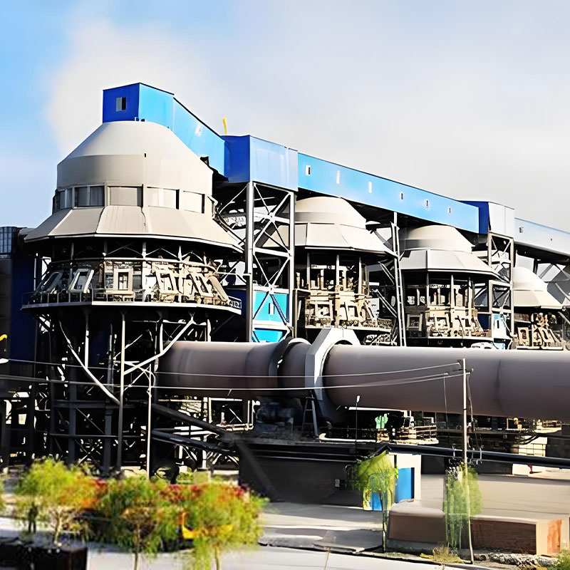
A rotary kiln is the textbook example. The kiln shell expands and contracts in every heat-up and cool-down cycle, the support piers take heavy point loads, and the entire line depends on the concrete foundation staying flat for decades. If uncontrolled cracking lets water into the base, freeze-thaw damage and grout deterioration under the support rollers can eventually pull the kiln out of alignment. That is why the structural design of the foundation and the mechanical design of the kiln should be reviewed as one system, beginning at the layout stage.
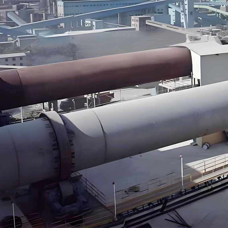
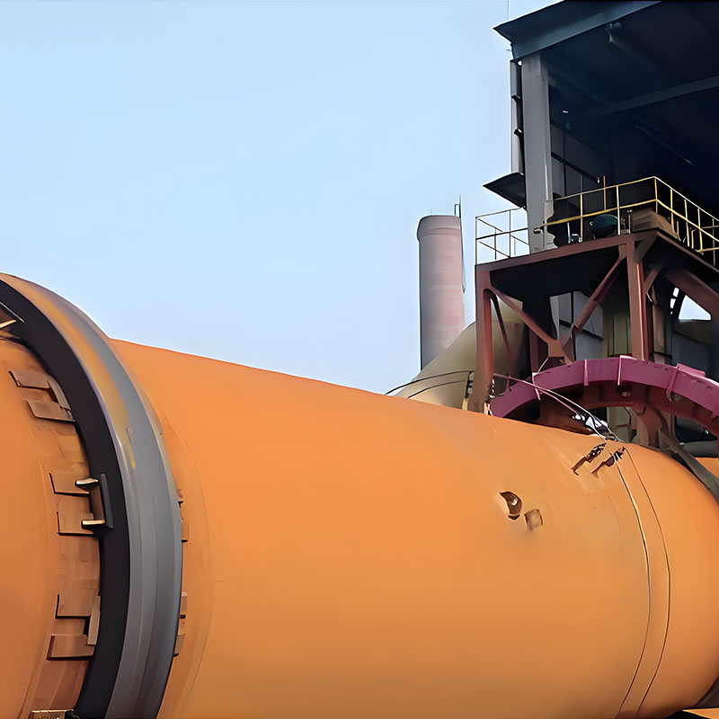
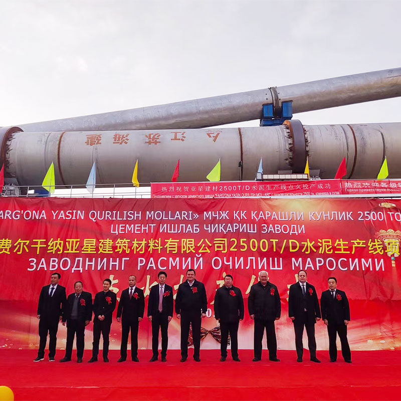 Rotary Kiln for Cement Clinker CalcinationThis rotary kiln includes advanced hydraulic wheel blocking, high-precision metering, and infrared scanning for calcining belt monitoring. Relevant here because its thermal cycling and point loads demand a stable, crack-controlled foundation.View Product →
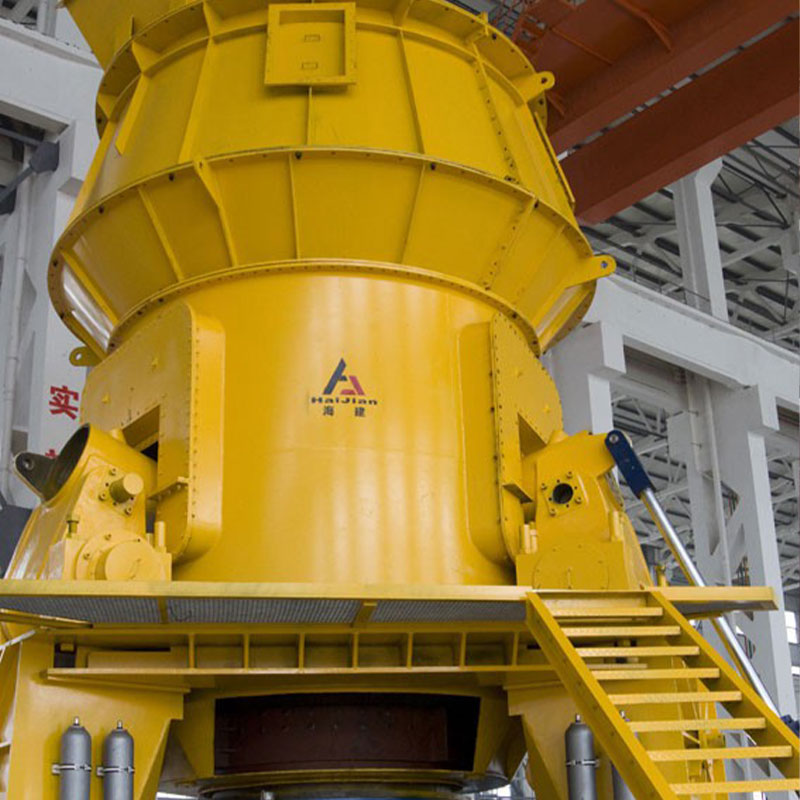
Rotating machines behave the same way. A cement mill imposes a large static load plus a continuous dynamic component from the grinding charge; a foundation that develops wide shrinkage cracks beneath the bearings becomes a vibration and alignment problem long before it becomes a structural emergency. Specifying crack control for those foundations is not an academic exercise—it is the difference between a plant that runs for decades and one that needs realignment every winter.
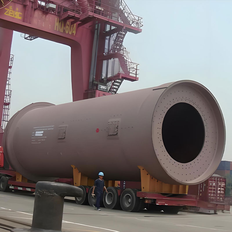
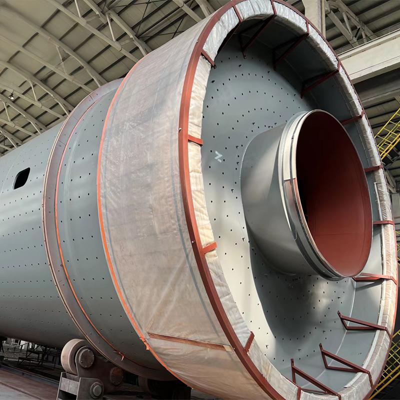 Cement Mill for Clinker GrindingThe cement mill grinds clinker and additives to target fineness, with a two-chamber structure and optional closed-circuit classifier. Given its heavy static and dynamic loads, it emphasizes why foundation crack control precedes alignment issues.View Product →
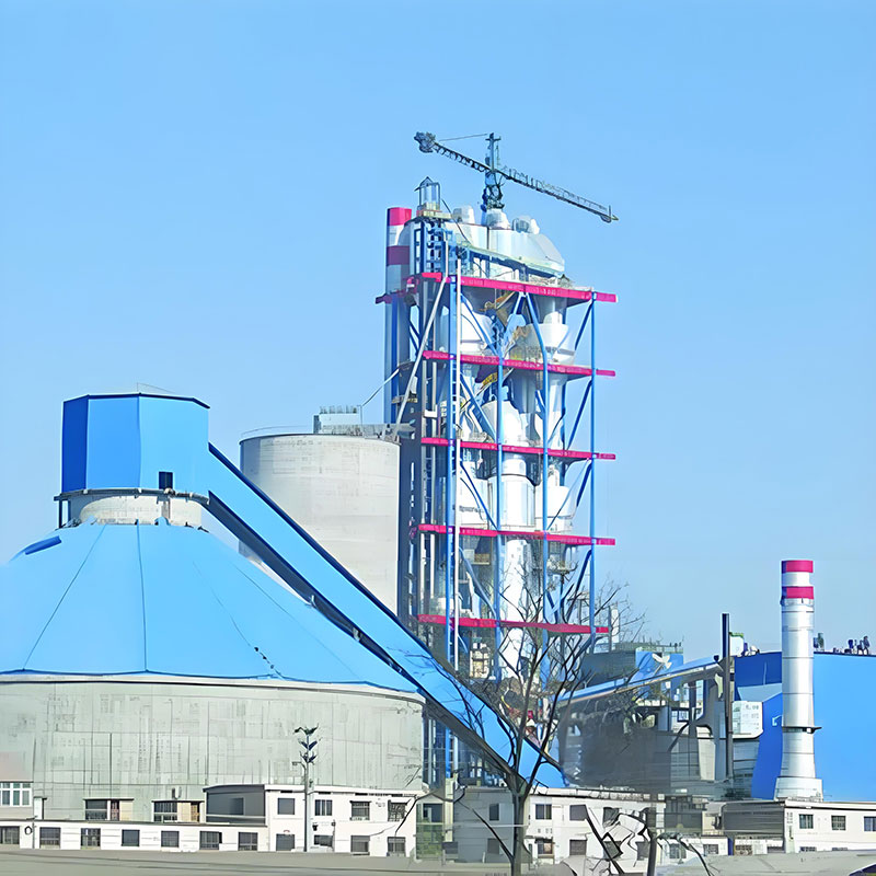
For plant owners, two practical conclusions follow. First, crack control belongs in the specification from day one. When a complete cement production line is supplied by a single manufacturer, the equipment and its concrete supports can be engineered together rather than reconciled after the fact; this is one reason why a manufacturer with full in-house engineering and fabrication capacity tends to produce fewer unpleasant surprises at the foundation–equipment interface.
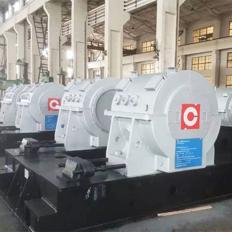
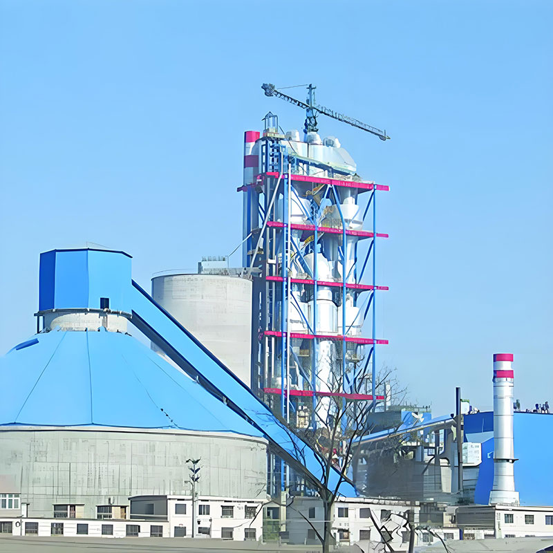 Complete Cement Production Line EquipmentA full cement production line covering crushing, preheating, calcining, grinding, and conveying, with process design and general contracting services. This single-supplier approach supports coordinated engineering of equipment and concrete supports from the start.View Product →
Second, the report gives maintenance teams a defensible inspection benchmark. An existing crack is not automatically a defect. If its width is within the ACI 224R-01 limit for the exposure, the cause is understood, and the crack has stabilized, the right decision is usually monitoring rather than repair. If the crack is growing, moving with temperature, or passing water, it needs a closer look and a considered repair.
The message of ACI 224R-01 has survived every revision: crack-free concrete is an unrealistic goal, but controlled cracking is an achievable one. Engineers who apply its crack-width limits, reinforcement rules, materials guidance, and construction practices get structures that stay watertight, durable, and serviceable for the full design life.
If you are planning a new production line, a grinding station, or a heavy equipment foundation, review your concrete specification against the same principles. And where the equipment meets the concrete, talk to the equipment manufacturer's engineering team early; it is far easier to adjust a drawing than to repair a foundation.
It is focused on the overall solution of dry bulk material port transfer system,
research and development, manufacturing, and service